Gentlemen,
I am relatively new to Ship technology and require your professional advice for my doubt on machine room layout for DE propulsion.
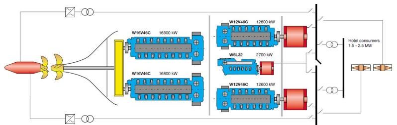
The following sketch (from a Wärtsilä brochure) depicts a layout in which the prime mover (W12C46C @ 12.6 MW) and associated alternator are separated by a watertight bulkhead :
IOW, this means that the prime mover and associated alternator are physically located in separate compartments.
I’m wondering how common such a configuration might be, and what would be its plus / minuses vs a more conventional layout where prime mover + alternator are physically located in the same compartement.
Thanks in advance.
Regards.
Matt.
I have seen it both ways. Generally the reasons for separate compartments are 2 fold. First and probably more important, is fire suppression & safety. Second is noise control.
[QUOTE=Chief Seadog;146466]I have seen it both ways. Generally the reasons for separate compartments are 2 fold. First and probably more important, is fire suppression & safety. Second is noise control.[/QUOTE]
Thanks for your interesting reply, Chief Seadog,
A couple more questions if I may :
[B]1)[/B] Before posting the OP, I tried to find real-world designs featuring separate compartments, but couldn’t find any. Off the top of your head, could you name some vessels featuring such separate compartments ?
[B]2)[/B] How is watertightness of the bulhead between alternator and prime-mover achieved ? Stuffing box ?
[QUOTE=Chief Seadog;146466]I have seen it both ways. Generally the reasons for separate compartments are 2 fold. First and probably more important, is fire suppression & safety. Second is noise control.[/QUOTE]
Thanks for your reply, Chief Seadog,
A couple more related question if I may :
[B]1) [/B]In case of separate compartments, how is bulkhead watertightness maintained (stuffing box ?)
[B]2)[/B] I’ve tried to locate real-world examples of vessels featuring separate compartments (prime-over located in one compartment, alternator in another one), but couldn’t find anything so far. Would you mind naming some of the vessels featuring separate compartments that you know of ?
[QUOTE=Matt R.;146495]
Would you mind naming some of the vessels featuring separate compartments that you know of ?
[/QUOTE]
Yeah, I’d like to see how and why that would be done too … mostly “why” since the generator is normally very closely coupled and the “how” is very costly and complex for minimal if any benefit.
I think that drawing is just the figment of a graphic artist’s imagination.
I would understand if this was an actual machinery arrangement and there was some other reason to have the transverse bulkhead between the engine and the alternator, for example insufficient space between the bulkheads to fit a full genset, but in a sketch like that it does not really make sense.
I think that drawing is just the figment of a graphic artist’s imagination.[/QUOTE]
I agree.
Divided machinery arrangements are used to provide duplication and continuity of services (propulsion / power / positioning) should one machinery space be disabled by fire or flooding.
This is seen in vessels specifically classed for such redundancy, and in certain DP vessels, most especially DP3.
But they are not arranged as seen in the sample sketch.
It could be an attempt to separate high voltage generators from the rest of the machinery spaces. Some ships are running 6kv and 11kv power generation nowadays.
Norwegian Star. I even have pics if you need proof. And since the Norwegian Star is one of a few in a series im sure the Jewel, Pearl, Dawn, etc are the same.
I’m 99% sure they are running 11kv generators. They have MAN 14 48/60’s, 4 of them. The newer vessels have a 5th engine.
Maybe they want to keep the alternator in an air conditioned apace. Even with an air/water heat exchanger these things still get hot. I’m with Steamer I think some new guy got overzealous with his CAD software.
[QUOTE=Kingrobby;146539]Norwegian Star. I even have pics if you need proof.[/QUOTE]
Sure, post one showing a bulkhead between the engine and the generator. Or show a photo of the “generator room” with a generator drive shaft penetrating the bulkhead.
[QUOTE=Kingrobby;146539]Norwegian Star. I even have pics if you need proof. And since the Norwegian Star is one of a few in a series im sure the Jewel, Pearl, Dawn, etc are the same.
I’m 99% sure they are running 11kv generators. They have MAN 14 48/60’s, 4 of them. The newer vessels have a 5th engine.[/QUOTE]
Hello Kingrobby,
Thanks for your reply.
I’d be delighted to take a look at your pics of Norwegian Star if you can post them. That way I’ll be able to figure out what the actual layout looks like.
This could be a work around for the 500m^3 engine room / water mist requirement. Either to cut the size of the space to below 500m^3 or to separate the generators from the risk associated with the water mist.
This could be an attempt at getting around the over 500m^3 machinery space water mist system requirement or an attempt to isolate the generators from the water mist system. If you sized the space appropriately you could have CO2 only on the generator side while the engines were covered by water mist.
I have two or 3 photos showing one of the engines shafts passing through a watertight bulkhead onboard the Star, I have 1 picture showing the shaft coming out and going into the generator. I am onboard my drillship right now so internet isnt good enough for me to upload the pics, but if you look at the links to my flickr photos you can see that I do have some engine room/machinery pics of the Star as well as other ships. I didnt upload the pics of the shafts cause frankly they arent that interesting to look at for most people. I WILL get you the pics though.
Engine rm humidity etc. seems only realistic reason. note also the gens are fwd of the eng., (longer wire runs?) … well, you never know what those designers are thinking, they persuade the guys with the $$ they have a good idea and someone will build the thing but I too think running a hi speed shaft thru a bulkhead a hassel, besides, the movers are in a closed environment, it’d be easier to find suitable air etc. for them than ‘move’ the engine room. weight distribution? gawd!
[QUOTE=jimrr;146827]Engine rm humidity etc. seems only realistic reason. note also the gens are fwd of the eng., (longer wire runs?) … well, you never know what those designers are thinking, they persuade the guys with the $$ they have a good idea and someone will build the thing but I too think running a hi speed shaft thru a bulkhead a hassel, besides, the movers are in a closed environment, it’d be easier to find suitable air etc. for them than ‘move’ the engine room. weight distribution? gawd![/QUOTE]
I think the main reasons the generators are mounted fwd of the engines is for easier exhaust stack routing for all the engines.
My current ship has 6 diesel/gens and the aft two are reversed in layout for just this reason. But the gens & engines are in the same spaces.
The Norwegian Star had its set up like this; generator space/bulkhead/engine room THEN engine room/bulkhead/generator space. I get off the boat Wednesday and will try to post pics then.