I assume having a flatter torque curve would be beneficial while maneuvering. I know it’s nice in a hybrid car for example accelerating on the on-ramp of the interstate. Doesn’t take a very big battery to last till the car is up to speed.
not much use without numbers…
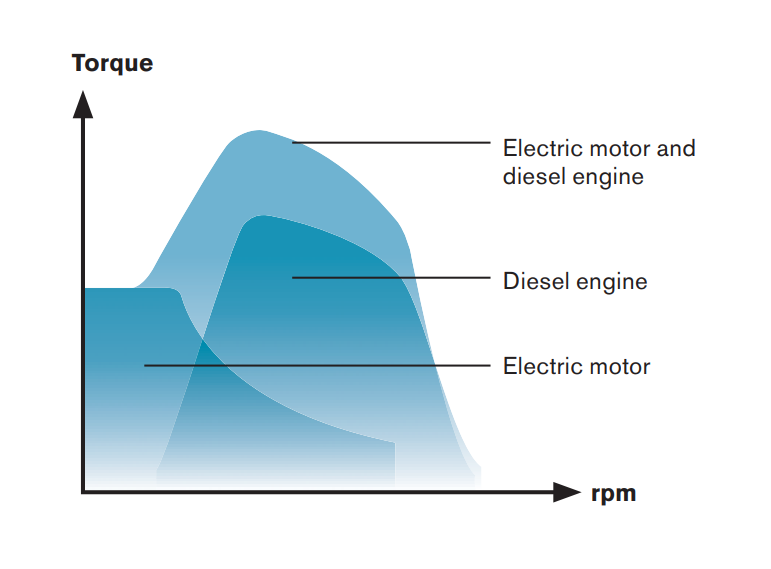
The diesels peak torque is higher than the electric so the electric can never do the same job unless the HP outputs are measured via gearboxes?
It makes for an interesting firefighting challenge. Self contained tank with plumbing set up to flood and also overflow for cooling would be ideal. Have new stability parameters already calculated while flooding and when full.
I don’t see that numbers are needed: electric + diesel > diesel.
In the c-max I drive the specs are gas 129 ft-lbs and electric is 117 ft-lbs.
I don’t know offhand what the gas torque is at RPMs close to idle speeds but whatever it is with the electric motor it going to be about 117 ft-lbs more than without.
Take this diagram;
Assume torque is less then half at low speed, that would give about 65 ft- lbs with gas alone and about 180 ft-lbs with both.
thats gasoline engine torque and HP graph, cant compare to diesel and electric as gasoline is all about speed not tug boat stuff
HP = work done
TQ = twisting force that could be at zero shaft speed so no work done
Not much energy available for regeneration on a marine vessel.
Here is a fairly good description of the options for hybrid drives:
My company installed emissions control systems on a 50m diesel electric yacht about 2 years ago. That vessel used 4 variable speed AC generators, feeding the hotel, charging batteries, and powering the two DC Azipods. It is an interesting vessel, the 4 gensets are mounted forward (2 on each side, one above the other) and the batteries are aft.
This is an illustration of the components of that system:
You guys are missing the fact that a large portion of time an OSV will be standing by offshore not performing any tasks. Optimal heading and relaxed positioning can be used so power requirements are very minimal for hours or days on end.
I worked alongside a few Italian AHTS’s that were set up with wing engines and twin input gearboxes so 2 large and 2 small engines.
They used very little fuel on standby whilst we had a 5000kw v12 chugging away.
It just cost more but that produces less emissions.
Why not a electric motor on a shaft so you could do variable speed when on electric only with gen sets but be able to put the main engines into gear when needed and the shaft electric motor could do fixed speed with the mains?
Add a battery and you get nice setup for DP.
2 independent power sources per shaft.
@Steamer I’m amazed at the advancements in electric drives since I retired. Are the transformers and filters to the 150kw grid basically isolation transformers?
like a welder they are not wound transformers of the old days they are switch mode power supplies and much smaller and lighter.
and expensive and how long do they last and what happens to them when the vessel is shutdown for long periods…
I remember the sparkies telling me if they shut down our rig ( 4160v) they would not be coming back to get it started again.
The gear not designed to be stored nor do the manufacturers have any experience with long term shutdown not to mention that model only made for one year…parts? knowledge? etc etc.
I know a DC grid system installed on a fleet of vessels by one of the EU major players, fault found during the FMEA took them 6 months of design changes to get it to work properly.
Like the Airbus 380 they were designing it as they built it…what could go wrong?
I’ve only worked with 480 and 600 volts systems. The advancements with VFDs in the first 10 years of this century was amazing. As compared to the old square wave shit, I was amazed how clean the waveform is now. Now, it’s improved inverters.
Essentially, yes, they are resin cast wire wound 3 phase transformers. They provide 400V 3 phase and 230V single phase for hotel and service loads. Nothing cutting edge about them.
This is the setup we have on the AHTS I work on, and the vessel on DP just chilling on the field. A battery to just take peaks would work perfect on the system.
In some parts of the world they install mooring buoys near offshore installations so that vessels on standby can tie up and shut down all their engines. They are expensive to install but pay for themselves eventually in fuel savings.
With cars there is “full hybrid” and “mild hybrid” having to do with the size of the battery. The full has a propulsion battery while the ‘mild’ version has a battery just big enough to run the car while stopped and to start the engine so that the engine can shut down at stop lights etc.
The Chevy Volt is an electric car with a 1.5 liter generator that can supply just enough electricity to keep going once the battery is spent (53 miles). The engine only connects direct to the wheels under very specific parameters.


